
 EN
EN



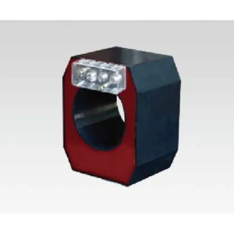
Installation errors represent one of the most significant yet preventable threats to current transformer performance and reliability in electrical systems. When a current transformer is improperly installed, the consequences ripple through measurement accuracy, equipment protection, and operational safety across an entire power distribution network. Understanding how installation mistakes directly compromise current transformer function is essential for electrical engineers, maintenance teams, and facility managers responsible for switchgear and metering systems.
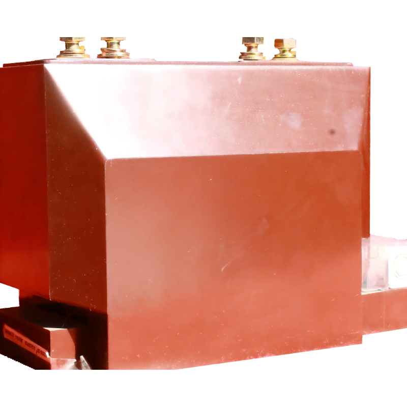
The performance of a current transformer depends critically on precise installation practices that respect electrical standards, mechanical alignment, and environmental conditions. Errors during installation introduce systematic problems that degrade accuracy, generate heat, cause premature aging, and potentially create safety hazards. By examining the specific installation errors that affect current transformer operation, organizations can implement preventive measures that protect equipment investment and maintain system reliability.
Improper Burden and Load Impedance Errors
Understanding Burden Impact on Current Transformer Performance
The burden of a current transformer refers to the impedance of the equipment connected to its secondary winding, including wiring, relays, meters, and monitoring devices. When a current transformer operates with burden exceeding its rated capacity, secondary current increases beyond design limits, causing core saturation and accuracy loss. Installation errors that miscalculate or underestimate burden create an immediate performance degradation that worsens over time as connected equipment accumulates additional load.
Technicians often fail to account for the total impedance when configuring a current transformer circuit, particularly in complex switchgear installations where multiple devices connect to the secondary side. If the actual burden exceeds the rated burden of the current transformer, the device generates excessive heat, accelerates insulation breakdown, and produces measurement errors that compromise protective relay coordination. Proper installation requires detailed burden calculations before commissioning any current transformer in service.
Secondary Wiring and Connection Losses
Secondary wiring quality and routing directly influence current transformer accuracy and performance during operation. Installing inadequate wire gauge, using corroded connectors, or creating poor terminations introduces additional impedance that contributes to burden errors. When secondary circuits contain loose connections or improper terminations, the current transformer experiences voltage drops that distort secondary current and reduce measurement precision across the entire system.
Installation errors often involve routing secondary wiring through environments with temperature extremes, moisture, or vibration without adequate protection. These conditions accelerate conductor oxidation, insulation degradation, and connection loosening that progressively degrade current transformer output quality. Proper installation practice requires secondary wire sizing calculations, protective conduit routing, and mechanical strain relief to maintain stable burden impedance throughout the service life of the current transformer.
Core Saturation and Magnetic Circuit Design Errors
Saturation Risk from Improper Turns Ratio Selection
Installation errors frequently stem from selecting an incorrect turns ratio for a current transformer application, creating a fundamental mismatch between the transformer design and actual system requirements. When the primary current exceeds the rating for which a current transformer was configured, core magnetic saturation occurs, causing secondary current nonlinearity and accuracy collapse. Choosing a turns ratio without proper load analysis represents a critical installation error that cannot be corrected through adjustment once the device operates under load.
Core saturation in a current transformer generates several cascading performance failures: reduced measurement accuracy, increased secondary current distortion, elevated core temperature, and accelerated aging of insulation materials. Installation professionals must verify that the selected current transformer turns ratio matches the maximum expected primary current under all operating conditions, including transient states and fault scenarios. Undersizing the primary rating of a current transformer guarantees saturation problems that progressively worsen as the device ages.
Magnetic Flux Leakage and Physical Positioning
Physical installation location and orientation of a current transformer significantly influence its magnetic characteristics and measurement accuracy. When a current transformer is positioned near large ferrous metal objects, power cables carrying high currents, or magnetic field sources, external magnetic interference couples into the core and distorts transformer operation. Installation errors involving inadequate spacing from interfering magnetic fields create measurement errors that fluctuate with changes in nearby equipment operation.
The mounting orientation of a current transformer must follow manufacturer specifications to ensure uniform magnetic flux distribution and minimize stray field coupling. Improper installation angles, tilted positioning, or tight physical packing in switchgear creates mechanical stress and asymmetric magnetic coupling that reduces current transformer accuracy under load. Proper installation practice requires maintaining specified clearance distances from ferrous structures and verifying that the current transformer core orientation aligns with installation guidelines.
Thermal and Environmental Installation Errors
Inadequate Heat Dissipation and Ventilation
A current transformer generates internal heat through core losses and secondary copper losses during normal operation, requiring adequate ventilation pathways to maintain safe operating temperatures. Installation errors that restrict air circulation around the transformer casing, block cooling vents, or enclose the device in unventilated enclosures cause excessive temperature rise that accelerates insulation degradation. When a current transformer operates consistently above its rated temperature limit, the oil or resin insulation degrades rapidly, shortening equipment lifespan and increasing failure risk.
Temperature-related installation errors create a slow but relentless degradation mechanism that remains invisible until failure occurs suddenly. Proper installation requires ensuring adequate clearance around the current transformer, unobstructed vent openings, and separation from heat-generating equipment such as power transformers or rectifiers. Installation engineers must verify that the thermal environment where the current transformer operates remains within design specifications throughout all seasons and operating cycles.
Moisture, Contamination, and Environmental Exposure
Installing a current transformer in environments with high humidity, salt spray, dust, or chemical contamination creates accelerated degradation of insulation, windings, and connections. Moisture ingress into the core or winding insulation system reduces dielectric breakdown strength and increases leakage current, progressively compromising current transformer performance and safety. Installation errors that fail to provide adequate environmental protection or moisture barriers expose the device to conditions that guarantee premature failure.
Proper installation practice includes evaluating the environmental classification of the installation location and selecting a current transformer rated for those specific conditions. Devices installed in outdoor, marine, or industrial atmospheres require enhanced corrosion protection, sealed compartments, and regular maintenance protocols that standard indoor installations do not necessitate. Installation errors related to environmental underestimation typically manifest months or years after commissioning, making prevention through proper initial setup crucial to long-term reliability.
Secondary Circuit and Earthing Installation Errors
Inadequate or Missing Secondary Earthing
The secondary circuit of a current transformer must be properly earthed to ensure operator safety and prevent dangerous voltage buildup during normal operation and fault conditions. Installation errors that fail to establish low-impedance earth connections or create multiple earthing points introduce ground loop currents that distort secondary measurements and create safety hazards. When a current transformer secondary circuit lacks proper earthing during installation, personnel working near the device face risk of electric shock, and measurement circuits malfunction under fault conditions.
Proper secondary earthing for a current transformer must be established at a single point, typically at the meter or relay terminal, using a dedicated earth conductor of specified gauge and impedance. Installation errors involving inadequate earth conductors, loose earth connections, or reliance on structural metalwork for earthing create unsafe conditions and unpredictable current transformer performance. Verification of secondary earthing continuity and impedance represents a critical commissioning step that installation teams must complete before placing any current transformer into service.
Open Secondary Circuit Prevention
An open-circuited secondary winding represents an extreme installation error condition that develops when secondary connections are severed, loose, or disconnected during maintenance or troubleshooting activities. When the secondary circuit of a current transformer is open, nearly all primary current transforms into magnetizing current, driving the core into extreme saturation and generating dangerous secondary voltages exceeding several thousand volts. Installation procedures must include safeguards and labeling to prevent accidental secondary circuit disconnection during equipment operation.
Proper installation practice includes installing secondary circuit protection devices, terminal shorting links, and warning labels that prevent open-circuit conditions from developing during maintenance work. The current transformer must never be energized with an open secondary circuit under any circumstances. Installation teams must establish lockout-tagout procedures and terminal designs that make accidental secondary disconnection extremely difficult, protecting both equipment and personnel from the dangerous conditions created by this critical error.
FAQ
How do installation errors in a current transformer affect measurement accuracy?
Installation errors compromise current transformer accuracy through multiple mechanisms: improper burden calculations cause core saturation, inadequate secondary wiring introduces impedance errors, incorrect positioning allows magnetic interference, and poor connections create voltage drops. Each of these errors distorts the secondary current signal, causing meters and protective relays to receive inaccurate measurements. The cumulative effect of installation errors can reduce current transformer accuracy to levels that render the device unsuitable for its intended application, requiring costly replacement or recalibration after commissioning discovery.
What is the most dangerous installation error for a current transformer?
The most dangerous installation error is an open secondary circuit, which generates extreme core saturation and dangerous high voltages that threaten personnel safety and equipment integrity. This error can occur when maintenance technicians accidentally disconnect secondary terminals without understanding the hazards of operating a current transformer with an open secondary side. Prevention requires clear labeling, terminal design that resists accidental disconnection, and training that emphasizes the critical importance of maintaining continuous secondary circuits throughout the service life of the current transformer.
How can installation teams verify that a current transformer is properly installed?
Verification of a current transformer installation requires comprehensive commissioning tests: measure secondary burden to confirm it remains within rated limits, verify secondary earthing continuity and impedance, confirm turns ratio accuracy through ratio testing, check core insulation resistance, measure thermal performance under loaded conditions, and validate accuracy performance against reference standards. These tests must be completed before placing the current transformer into service and documented to establish baseline performance data for future maintenance reference and trouble diagnosis.