


High voltage substations represent the backbone of modern electrical infrastructure, requiring specialized components that can withstand extreme operational conditions while maintaining exceptional reliability. Among these critical components, the gis bushing stands out as an essential element that enables safe and efficient power transmission in gas-insulated switchgear systems. These sophisticated devices serve as the crucial interface between the gas-insulated environment inside the switchgear and the external air-insulated connections, making their design and performance characteristics absolutely vital for substation operations.
Understanding GIS Bushing Technology and Construction
Core Design Principles of Gas Insulated Systems
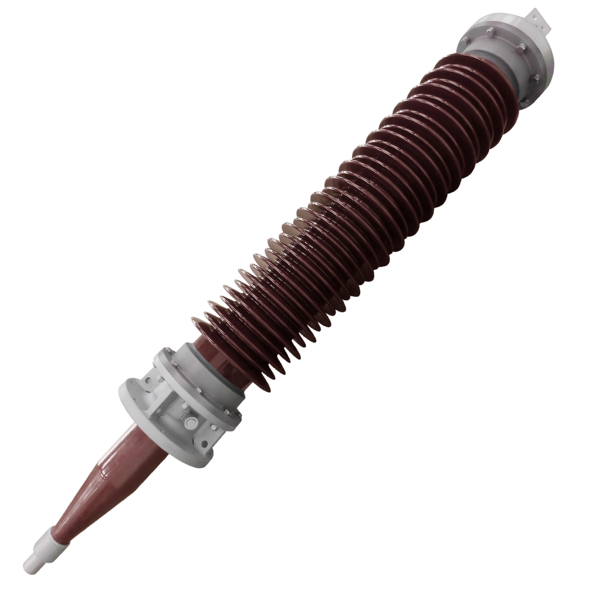
The fundamental design of a gis bushing incorporates advanced insulation technologies that leverage sulfur hexafluoride gas properties to achieve superior dielectric performance. This specialized construction allows for significant space reduction compared to conventional air-insulated systems while maintaining the highest safety standards. The bushing's internal structure features carefully engineered electric field distribution that prevents partial discharge and corona formation under normal operating conditions.
Modern gis bushing designs utilize composite materials that combine excellent mechanical strength with outstanding electrical properties. The insulator body typically consists of high-performance polymeric materials or porcelain, depending on specific application requirements and environmental conditions. These materials are selected for their ability to withstand both electrical stress and mechanical forces encountered in high voltage operations.
Advanced Insulation Materials and Manufacturing Processes
The manufacturing process of a high-quality gis bushing involves precision engineering and strict quality control measures throughout every production stage. Advanced molding techniques ensure uniform material distribution and eliminate potential weak points that could compromise performance. The conductor assembly within the bushing undergoes specialized treatments to minimize surface irregularities that might cause electric field concentration.
Quality assurance protocols include comprehensive testing procedures that verify electrical, mechanical, and thermal performance characteristics. Each gis bushing must pass rigorous impulse tests, power frequency tests, and partial discharge measurements before approval for installation. These testing procedures simulate real-world operating conditions and ensure long-term reliability in demanding substation environments.
Electrical Performance Characteristics in High Voltage Applications
Dielectric Strength and Insulation Coordination
The exceptional dielectric strength of a properly designed gis bushing enables safe operation at voltages ranging from medium voltage applications up to ultra-high voltage systems exceeding 800 kV. This performance capability results from careful insulation coordination that considers both internal gas pressure and external environmental factors. The bushing's ability to maintain consistent insulation performance across varying temperature and humidity conditions makes it particularly suitable for outdoor substation installations.
Electric field management within the gis bushing structure utilizes sophisticated geometric optimization and material selection to ensure uniform stress distribution. This approach prevents the formation of high-stress regions that could lead to premature aging or failure. The resulting design provides exceptional reliability even under severe overvoltage conditions that may occur during system transients or fault conditions.
Thermal Management and Current Carrying Capacity
Thermal performance represents another critical aspect of gis bushing design, as these components must safely carry substantial continuous currents while dissipating generated heat effectively. The conductor design incorporates optimized cross-sectional areas and materials with excellent thermal conductivity to minimize temperature rise under rated current conditions. Advanced thermal modeling ensures that hotspot temperatures remain within acceptable limits throughout the expected service life.
The thermal expansion characteristics of the gis bushing must be carefully coordinated with the surrounding switchgear structure to prevent mechanical stress accumulation during temperature cycling. Flexible connection designs accommodate thermal movement while maintaining electrical contact integrity and gas seal performance. This thermal management approach ensures reliable operation across the full range of ambient temperature conditions typically encountered in substation environments.
Mechanical Design Features for Substation Environments
Structural Integrity and Seismic Resistance
High voltage substations often operate in challenging environments where mechanical reliability is as important as electrical performance. The gis bushing design must withstand significant mechanical loads including conductor tensions, wind forces, and seismic accelerations without compromising operational integrity. Modern designs incorporate advanced finite element analysis to optimize structural geometry and material distribution for maximum strength-to-weight ratios.
Seismic qualification of gis bushing assemblies requires comprehensive testing that simulates earthquake conditions with appropriate response spectra and duration characteristics. The resulting designs demonstrate exceptional resilience to ground motion while maintaining both electrical performance and gas containment capabilities. This seismic resistance capability is particularly important for installations in regions with high seismic activity where substation reliability is critical for post-event recovery operations.
Environmental Protection and Contamination Resistance
Outdoor substation environments expose equipment to various contamination sources including industrial pollutants, salt spray in coastal areas, and natural debris that can accumulate on insulator surfaces. The external profile of a gis bushing incorporates specialized shed designs that promote self-cleaning and prevent contamination buildup that could reduce flashover performance.
Advanced surface treatments and material formulations provide enhanced resistance to tracking and erosion caused by electrical discharge activity in contaminated conditions. These protective measures extend service life and reduce maintenance requirements, contributing to improved overall system reliability and reduced lifecycle costs. The hydrophobic properties of modern insulator materials help maintain performance even in high humidity or wet conditions.
Installation and Integration Considerations
Interface Requirements with Gas Insulated Switchgear
Successful integration of a gis bushing into gas-insulated switchgear systems requires careful attention to interface specifications and installation procedures. The gas seal integrity must be maintained throughout installation and subsequent operation to prevent SF6 gas leakage that could compromise both performance and environmental compliance. Specialized installation tools and procedures ensure proper assembly without damage to critical sealing surfaces.
The mechanical interface between the gis bushing and switchgear enclosure must accommodate thermal expansion differences while maintaining electrical continuity and gas containment. Precision manufacturing tolerances ensure proper fit and alignment during installation, while standardized connection methods facilitate field assembly and future maintenance activities. Quality control procedures verify proper installation before system energization.
External Connection Methods and Accessories
The external terminal of a gis bushing must accommodate various connection methods including overhead transmission lines, underground cables, and flexible bus connections to other substation equipment. Standardized connection hardware ensures compatibility with existing infrastructure while providing reliable electrical contact under all operating conditions. Corona control accessories may be required for higher voltage applications to prevent radio interference and ensure safe operation.
Weather protection systems including surge arresters and wildlife guards are often integrated with gis bushing installations to enhance system reliability and safety. These accessories must be coordinated with the bushing design to ensure proper electrical clearances and mechanical compatibility. Installation procedures include verification of all accessory connections and performance testing to confirm system readiness for service.
Performance Testing and Quality Assurance
Factory Testing Protocols and Standards
Comprehensive factory testing of each gis bushing ensures compliance with international standards and customer specifications before shipment to installation sites. Standard test procedures include routine electrical tests such as power frequency voltage application and partial discharge measurements that verify basic insulation integrity. Type tests demonstrate capability to withstand impulse voltages, short-circuit currents, and mechanical loads representative of actual service conditions.
Advanced diagnostic testing techniques including tan delta measurements and frequency domain spectroscopy provide detailed information about insulation condition and aging characteristics. These tests help identify potential quality issues before installation and establish baseline performance data for future condition monitoring programs. Statistical analysis of test results ensures consistent product quality and identifies opportunities for continuous improvement.
Field Testing and Commissioning Procedures
After installation, field testing of the complete gis bushing assembly verifies proper installation and system integration before energization. These tests typically include insulation resistance measurements, power frequency voltage tests, and SF6 gas quality verification to ensure system readiness. Specialized test equipment designed for gas-insulated systems enables thorough evaluation without compromising gas containment or system integrity.
Commissioning procedures also include functional testing of any integrated monitoring systems or condition assessment equipment associated with the gis bushing installation. Documentation of test results provides important baseline information for future maintenance planning and condition assessment activities. Proper commissioning ensures optimal performance and reliability throughout the expected service life.
Maintenance Strategies and Lifecycle Management
Condition Monitoring and Diagnostic Techniques
Modern condition monitoring approaches for gis bushing systems utilize both online and offline diagnostic techniques to assess performance and identify potential issues before they affect system reliability. Online monitoring systems continuously measure parameters such as partial discharge activity, gas pressure, and temperature to detect changes that might indicate developing problems. These systems provide early warning capabilities that enable proactive maintenance scheduling.
Periodic offline testing using advanced diagnostic equipment provides detailed assessment of insulation condition and mechanical integrity. Techniques such as dielectric spectroscopy and acoustic emission analysis can detect internal changes that precede visible external symptoms. This comprehensive monitoring approach enables optimized maintenance strategies that balance reliability requirements with economic considerations.
Preventive Maintenance and Service Life Extension
Preventive maintenance programs for gis bushing installations focus on maintaining optimal operating conditions and preventing degradation that could lead to premature failure. Regular inspection of external surfaces, connection hardware, and associated accessories helps identify issues that require attention before they affect performance. Gas quality monitoring ensures that SF6 characteristics remain within acceptable limits for continued reliable operation.
Service life extension strategies may include refurbishment of specific components or upgrade of monitoring systems to improve performance visibility. Advanced materials and improved designs incorporated in replacement components can enhance overall system capability while maintaining compatibility with existing installations. These approaches help maximize return on infrastructure investments while ensuring continued reliable service.
FAQ
What are the primary advantages of using GIS bushings in high voltage substations?
GIS bushings offer several key advantages including significantly reduced space requirements compared to air-insulated alternatives, enhanced reliability through enclosed gas insulation, and improved safety through elimination of external live parts. The compact design enables substations in urban areas where land availability is limited, while the enclosed construction provides better protection against environmental contamination and wildlife contact. Additionally, the reduced maintenance requirements and longer service life contribute to lower lifecycle costs.
How do environmental conditions affect GIS bushing performance and selection?
Environmental factors such as temperature extremes, humidity levels, contamination sources, and seismic activity all influence gis bushing selection and design requirements. Coastal installations require enhanced corrosion resistance and contamination performance, while areas with extreme temperature variations need designs that accommodate thermal cycling effects. Seismically active regions require bushings with enhanced mechanical strength and flexible connection methods to withstand ground motion without damage.
What maintenance activities are typically required for GIS bushing systems?
Routine maintenance for gis bushing systems includes visual inspection of external components, verification of gas pressure and quality, testing of monitoring systems, and periodic electrical testing to assess insulation condition. The enclosed design significantly reduces maintenance compared to air-insulated systems, but regular attention to gas seals, external connections, and condition monitoring equipment ensures optimal long-term performance. Most maintenance activities can be performed without system outages using appropriate safety procedures.
How long can GIS bushings be expected to operate reliably in substation service?
High-quality gis bushing designs typically provide reliable service for 30 to 40 years or more when properly maintained and operated within specified parameters. The actual service life depends on factors including operating voltage, current loading, environmental conditions, and maintenance quality. Modern designs incorporate materials and construction methods that enhance aging resistance and provide excellent long-term stability under normal operating conditions, making them suitable for critical infrastructure applications where extended service life is essential.
Table of Contents
- Understanding GIS Bushing Technology and Construction
- Electrical Performance Characteristics in High Voltage Applications
- Mechanical Design Features for Substation Environments
- Installation and Integration Considerations
- Performance Testing and Quality Assurance
- Maintenance Strategies and Lifecycle Management
-
FAQ
- What are the primary advantages of using GIS bushings in high voltage substations?
- How do environmental conditions affect GIS bushing performance and selection?
- What maintenance activities are typically required for GIS bushing systems?
- How long can GIS bushings be expected to operate reliably in substation service?