
 EN



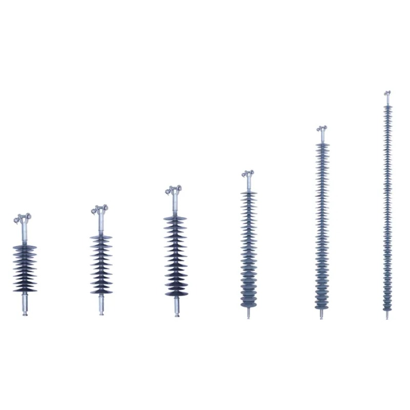
The structural integrity of electrical systems depends critically on understanding what mechanical loads a composite insulator can withstand. Unlike traditional porcelain or glass insulators, composite insulators offer distinct mechanical properties that determine their safe operational limits in power transmission and distribution networks. This guide explores the mechanical load capacity of composite insulators, including tensile strength, bending loads, and environmental stress factors that affect their performance over time.
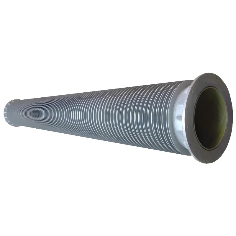
A composite insulator is engineered to balance electrical insulation with mechanical strength, making it suitable for demanding installations where conventional materials may fail. Understanding the load ratings of a composite insulator ensures proper selection for specific applications and prevents premature failure. The mechanical performance of a composite insulator varies based on material composition, core design, and manufacturing standards that comply with international specifications.
Tensile Strength and Breaking Loads
Maximum Tensile Capacity
The tensile strength of a composite insulator represents its ability to resist axial pulling forces along the longitudinal axis. Modern composite insulators typically achieve tensile strengths ranging from 70 kiloNewtons to over 210 kiloNewtons, depending on core material and diameter specifications. The composite insulator core, usually made from fiberglass-reinforced epoxy resin, provides the primary load-bearing structure. This material composition allows a composite insulator to deliver high strength-to-weight ratios that exceed traditional porcelain designs.
Mechanical Design Margins
Engineers apply safety factors when specifying a composite insulator for field installations. The mechanical working load typically represents 20 to 25 percent of the ultimate tensile capacity, ensuring that the composite insulator maintains structural integrity under normal conditions plus environmental stresses. When selecting a composite insulator, utilities verify that the applied mechanical load remains well below the safety-adjusted threshold. This practice protects the composite insulator from failure due to unexpected loads or material degradation over decades of service life.
Environmental and Cyclic Load Effects
Temperature Influence on Mechanical Properties
Temperature variations significantly impact the mechanical load capacity of a composite insulator. At elevated temperatures, the resin matrix of the composite insulator becomes slightly more compliant, reducing its effective modulus of elasticity. Conversely, at extremely low temperatures, the composite insulator material becomes more brittle, potentially reducing impact resilience. A properly designed composite insulator accounts for the operating temperature range through material selection and core geometry that maintains adequate mechanical reserve across seasonal and climatic variations expected in the installation region.
Creep and Long-Term Performance
Creep behavior describes the gradual elongation of a composite insulator under sustained mechanical load over extended periods. The composite insulator core material exhibits measurable creep, particularly under continuous stress at elevated temperatures. Long-term field data shows that a composite insulator typically experiences creep rates of less than 2 percent of initial elongation over 50 years when loaded at 25 percent of ultimate strength. This predictable behavior of a composite insulator enables utilities to factor long-term deformation into design calculations, ensuring that mechanical clearances and electrical distances remain adequate throughout the service life.
Bending and Lateral Load Considerations
Cantilever Load Ratings
Composite insulators must withstand not only vertical and axial loads but also lateral bending forces from wind, ice accumulation, and equipment vibration. A composite insulator installed in a cantilever configuration, such as on strain towers or suspension structures, experiences complex stress patterns combining bending and tension. The bending moment capacity of a composite insulator depends on its diameter, material properties, and the distance from the point of support. Manufacturers provide detailed mechanical load charts for different composite insulator designs, specifying allowable cantilever loads at various distances from the mounting hardware. This composite insulator data enables engineers to validate that wind and ice loads remain within safe operating limits for the intended tower geometry.
Dynamic Loading and Vibration Resistance
Power system components generate vibration and dynamic loads that test the fatigue resistance of a composite insulator. Aeolian vibration, caused by wind flowing across overhead conductors, creates cyclic bending stresses that can accumulate over time. A well-designed composite insulator maintains adequate fatigue strength to withstand millions of vibration cycles without developing cracks or permanent deformation. Laboratory testing of a composite insulator under controlled cyclic loads confirms that the material exhibits excellent fatigue resistance compared to brittle alternatives, reducing the risk of unexpected service interruptions due to mechanical failure.
Material and Design Factors Affecting Load Capacity
Core Material Composition
The selection of core material directly influences the mechanical load capacity of a composite insulator. Fiberglass-reinforced epoxy remains the industry standard because a composite insulator made with this material achieves optimal balance between electrical insulation and mechanical strength. The fiber orientation within the composite insulator core affects directional load-bearing ability, with longitudinal fibers providing superior tensile strength. Some applications require specialized composite insulator designs with enhanced mechanical properties through modified resin systems or increased fiber content, enabling higher load ratings for particularly demanding installations or extreme environmental conditions.
Hardware and Interface Design
The mechanical connection between a composite insulator and hardware components significantly affects overall load-carrying capability. Stress concentration at the interface between the composite insulator and metal fittings can reduce effective strength if not properly engineered. Modern composite insulator designs incorporate stress-relieving shapes and bonding techniques that distribute loads gradually across the junction zone. This thoughtful composite insulator engineering prevents premature failure at the attachment points, allowing the full tensile capacity of the core material to be realized during service.
FAQ
What is the typical tensile strength of a composite insulator used in transmission lines?
Standard composite insulators for high-voltage transmission typically feature tensile strengths between 120 and 210 kiloNewtons, depending on the core diameter and material specification. The exact tensile strength of any composite insulator is documented in the manufacturer's technical datasheet and confirms compliance with relevant international standards such as IEC 61109.
How do temperature changes affect the mechanical load capacity of a composite insulator?
Temperature changes modify the mechanical properties of a composite insulator by altering the resin matrix characteristics. At higher temperatures, a composite insulator becomes slightly more compliant and experiences increased creep rates, while cold conditions can increase brittleness. This composite insulator behavior is accounted for through safety factors and material selection processes that ensure adequate mechanical reserve across the expected operating temperature range.
Can a composite insulator be used in locations with frequent wind or heavy ice loads?
Yes, a composite insulator can be effectively used in challenging environments with high wind and ice loads, provided that the specific design is rated for those conditions. Engineers select a composite insulator with appropriate bending moment capacity and validate that the combined mechanical stresses from environmental factors remain below safety-adjusted thresholds through detailed load calculations and manufacturer specifications.