
 EN
EN



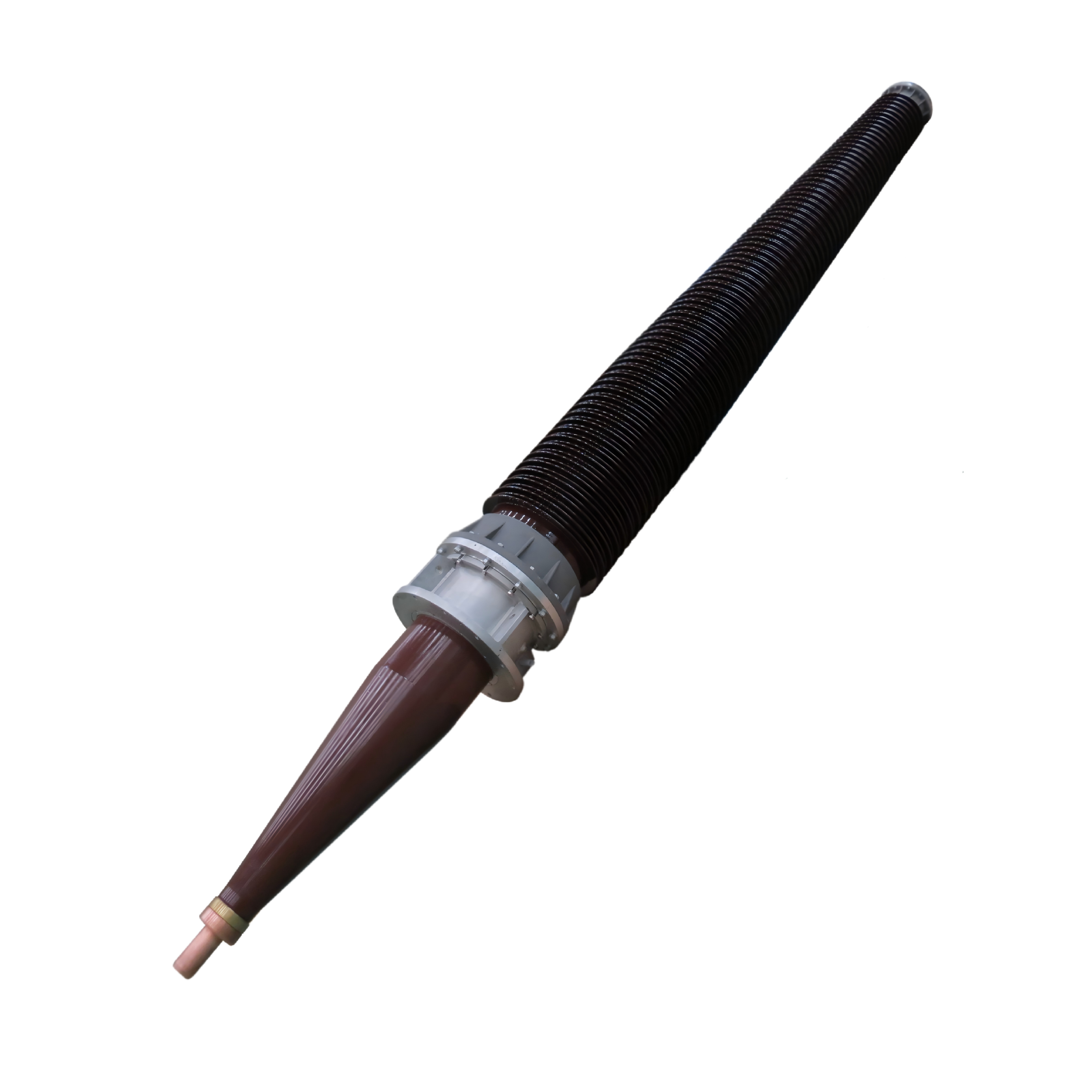
The reliability of your GIS bushing directly impacts the overall performance and safety of gas-insulated switchgear systems. A faulty GIS bushing can compromise electrical insulation, reduce operational efficiency, and create costly downtime risks across your power distribution network. Understanding and implementing proper testing methods is essential to maintaining GIS bushing integrity throughout its operational lifecycle. This article explores the critical testing protocols that electrical utilities and industrial facilities use to validate GIS bushing performance and prevent unexpected failures in high-voltage environments.
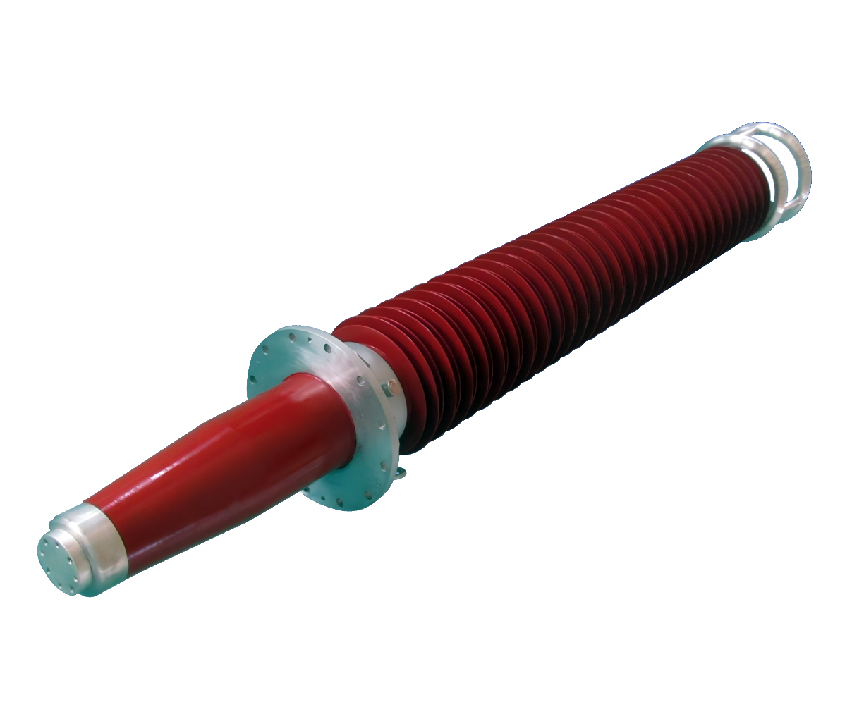
Testing a GIS bushing involves multiple specialized procedures that evaluate electrical, thermal, and mechanical characteristics under simulated and actual operating conditions. These testing regimens comply with international standards such as IEC and IEEE protocols, ensuring that every GIS bushing meets stringent performance criteria before installation and during regular maintenance intervals. By implementing systematic GIS bushing testing, you reduce failure risk, extend equipment lifespan, and maintain compliance with industry safety standards. The comprehensive approach to GIS bushing validation protects your investment and ensures uninterrupted power system reliability.
Electrical Testing of GIS Bushing Performance
High-Voltage Dielectric Strength Assessment
Dielectric strength testing is one of the most critical evaluations for any GIS bushing system. This test applies gradually increasing voltage across the bushing's insulation structure to determine its breakdown threshold and withstand capability. Engineers conduct this GIS bushing assessment under controlled laboratory conditions, monitoring for any signs of partial discharge or electrical leakage that might indicate internal defects. The GIS bushing must maintain its dielectric properties across rated voltage levels plus a defined safety margin, typically 150 percent of operational voltage for factory acceptance testing.
Partial discharge detection during GIS bushing testing reveals microscopic defects in the insulation material that could eventually lead to catastrophic failure. Modern testing equipment measures discharge magnitude, frequency, and phase angle to quantify the severity of any internal anomalies. A GIS bushing with excessive partial discharge activity is rejected during factory testing, preventing problematic units from reaching field installations. This preventive approach saves utilities from emergency replacements and safety incidents that result from insulation breakdown.
Insulation Resistance and Moisture Analysis
Measuring insulation resistance provides insight into the overall condition of a GIS bushing's electrical properties and its resistance to moisture intrusion. Technicians use megohm meters to test the GIS bushing at specific voltages, typically 500 volts or 1000 volts depending on bushing voltage class. Results are compared against established baselines for similar GIS bushing designs to identify anomalies or degradation. Low insulation resistance in a GIS bushing can indicate contamination, moisture absorption, or internal damage that requires immediate attention.
Water content analysis of the GIS bushing insulation material is performed using Karl Fischer titration methods, a precise chemical technique that quantifies moisture levels in the solid insulation and any liquid components. Excessive moisture in a GIS bushing compromises its electrical properties and accelerates aging processes. Testing protocols specify maximum allowable moisture content for each GIS bushing type, ensuring that only properly dried units are deployed in service. This moisture control is especially critical for GIS bushings operating in high-humidity environments or in regions experiencing significant temperature fluctuations.
Thermal and Mechanical Testing Protocols
Temperature Rise and Thermal Cycling Evaluation
Temperature rise testing validates that a GIS bushing can safely dissipate heat generated by electrical current flowing through its conductor without exceeding design temperature limits. Load current is applied to the GIS bushing for an extended period while surface and core temperatures are continuously monitored with thermocouples and infrared sensors. The GIS bushing must demonstrate stable thermal performance, with temperature stabilizing below maximum design specifications. This testing ensures that normal operational currents do not create hotspots or accelerate insulation degradation through thermal stress.
Thermal cycling testing subjects the GIS bushing to repeated temperature transitions to simulate seasonal changes and operational variations. A GIS bushing is cycled between extreme temperature limits, typically cold soaking followed by heated current application, across multiple iterations. This GIS bushing assessment identifies potential mechanical failures, seal integrity problems, or material separation that might occur due to differential thermal expansion. Units that pass thermal cycling demonstrate robust mechanical construction and material compatibility essential for long-term field reliability.
Mechanical Stress and Vibration Resistance
Mechanical vibration testing ensures that a GIS bushing remains structurally sound when subjected to operational vibrations from switching events, fault currents, and electromagnetic forces. A GIS bushing is mounted on a vibration table and exposed to frequencies and amplitudes that simulate real power system conditions. Engineers monitor the GIS bushing for any mechanical loosening, connector movement, or structural fatigue during this testing protocol. Robust GIS bushing design must withstand thousands of switching cycles and transient electromagnetic forces without developing loose connections or internal movement.
Mechanical compression and tensile testing of GIS bushing materials provides data on material strength, elasticity, and failure points under extreme stress conditions. These tests validate that the porcelain or composite insulator body of a GIS bushing can tolerate mechanical shock, installation forces, and routine maintenance handling without cracking or delamination. A GIS bushing that passes comprehensive mechanical testing demonstrates superior construction quality and durability for field applications spanning decades of service life.
Factory Acceptance and Field Verification Testing
Factory Acceptance Test Protocols
Factory acceptance testing (FAT) represents the complete validation suite performed before a GIS bushing leaves the manufacturing facility. Every GIS bushing undergoes electrical, thermal, mechanical, and dimensional verification according to applicable standards such as IEC 60137 for capacitive bushings or API 5L specifications for specialized applications. A GIS bushing is documented with detailed test reports, thermal images, and performance curves that become part of its permanent technical record. These comprehensive FAT results provide buyers with confidence that each GIS bushing meets contracted specifications and performance guarantees.
The FAT report for a GIS bushing includes baseline measurements that allow future field testing to identify degradation trends over the equipment's operational life. Purchasing specifications should explicitly require full GIS bushing documentation of factory testing results before acceptance. This documentation becomes invaluable for troubleshooting, warranty claims, and maintenance planning throughout the GIS bushing's service period. Organizations that enforce strict FAT requirements on all GIS bushing purchases experience fewer field failures and better long-term asset management outcomes.
On-Site Commissioning and Periodic Maintenance Testing
Commissioning testing of a GIS bushing after installation validates that field conditions have not damaged the equipment during transportation or installation procedures. Critical tests include insulation resistance measurement, power factor analysis, and capacitance comparison against factory test data. A GIS bushing that shows significant deviation from factory baseline values may require replacement before being energized. This on-site commissioning prevents early failures that would be catastrophic if discovered only after the GIS bushing enters regular service.
Periodic maintenance testing of a GIS bushing throughout its operational life provides early warning of degradation or emerging problems requiring intervention. Annual or biennial testing of insulation resistance, power factor, and capacitance trends identifies moisture ingress, contamination, or material degradation patterns in a GIS bushing before they become critical. Field testing of a GIS bushing can be performed using portable equipment during planned maintenance windows. Utilities that implement rigorous periodic GIS bushing testing programs extend equipment lifespan and avoid catastrophic failures that disrupt power delivery to critical customers.
FAQ
What are the primary indicators that a GIS bushing requires testing or replacement?
Visual indicators such as cracks, porcelain chips, seal damage, or oil leakage signal that a GIS bushing needs immediate evaluation. Electrical indicators include unusually high partial discharge readings, significantly reduced insulation resistance, or elevated power factor compared to historical trends. Thermal indicators such as hot spots detected during infrared scanning or elevated surface temperatures during load current conditions suggest internal problems with the GIS bushing. Any combination of visual, electrical, or thermal warning signs warrants comprehensive testing to determine whether a GIS bushing can continue operating safely or requires replacement.
How frequently should GIS bushing testing be performed in active power systems?
Most utilities and industrial facilities perform comprehensive GIS bushing testing on a two-year maintenance cycle, with some critical applications testing annually or biannually depending on environmental conditions and operational stress levels. Newly installed GIS bushings require baseline commissioning testing before energization and initial maintenance testing within twelve months of service entry. Environmental factors such as coastal salt spray, industrial pollution, high humidity, or extreme temperature variations may warrant more frequent GIS bushing testing intervals. Maintenance programs should include routine oil analysis for liquid-filled GIS bushings and regular thermal imaging surveys to detect emerging problems before scheduled maintenance windows.
Can field testing methods provide the same level of validation as factory acceptance testing for a GIS bushing?
Field testing of a GIS bushing provides excellent trending data and early warning of degradation but cannot fully replicate all factory testing conditions due to environmental constraints and equipment limitations. Factory testing of a GIS bushing includes destructive testing limits, extreme environmental conditions, and full-duration thermal cycling that cannot be safely performed on installed equipment. However, periodic field testing of a GIS bushing through insulation resistance measurement, power factor analysis, and partial discharge monitoring provides sufficient data to track condition trends and identify problems well before critical failure occurs. Combining factory acceptance data with systematic field testing creates a comprehensive lifecycle monitoring program for GIS bushing reliability and safety.