
 EN
EN



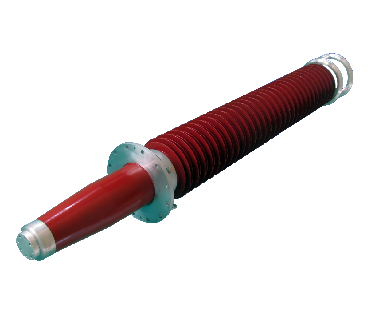
Compact substations represent a fundamental shift in electrical infrastructure design, and the gis bushing stands at the center of this transformation. Modern utilities face increasing pressure to maximize efficiency while minimizing physical footprint, and gis bushing technology directly addresses this challenge. The integration of high-performance gis bushing components enables substations to deliver reliable power distribution in constrained urban and industrial environments where traditional air-insulated designs prove impractical or economically unfeasible.
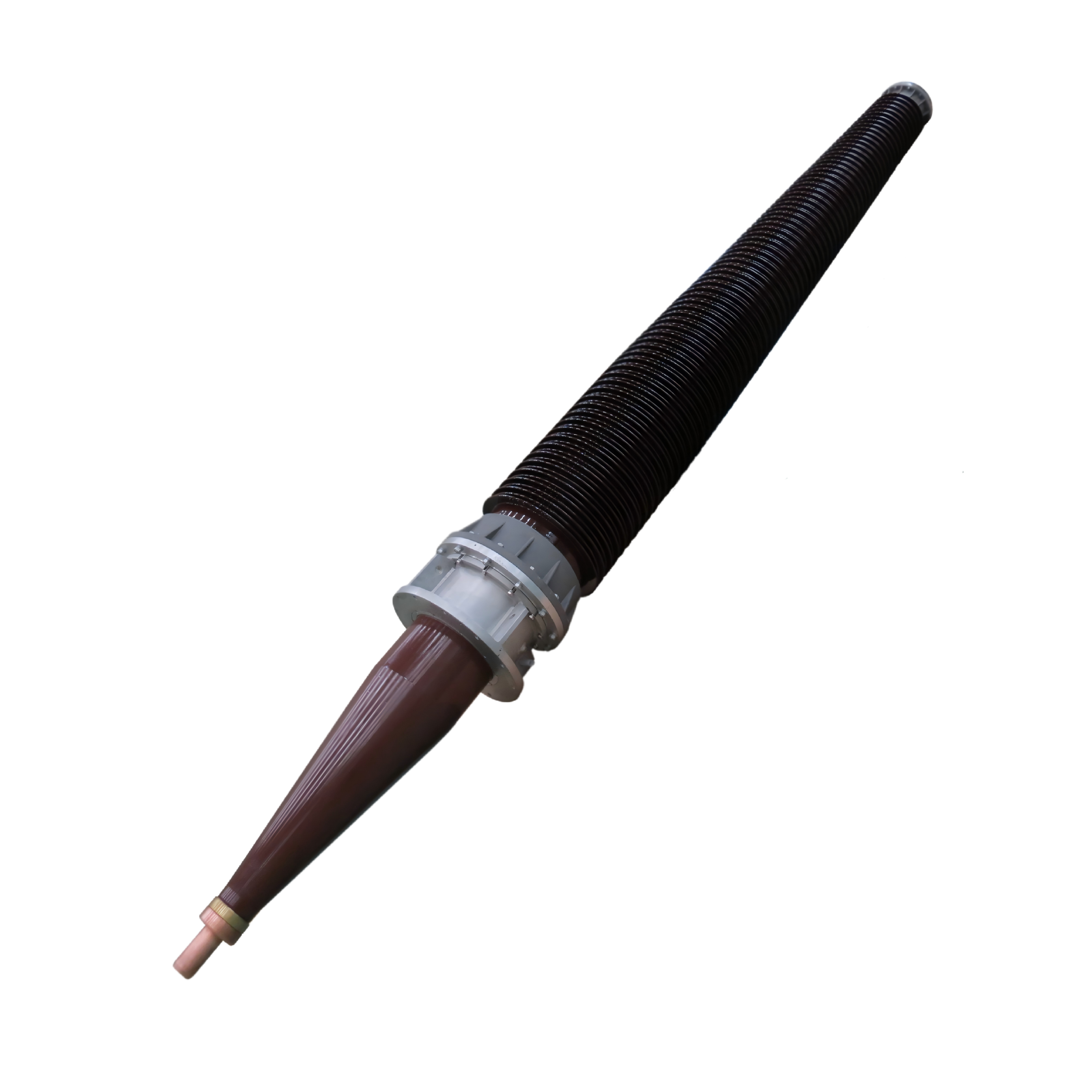
A gis bushing serves as a critical interface component within gas-insulated switchgear systems, managing the transition between internal insulated conductors and external connection terminals. The engineering precision required in a gis bushing directly impacts the reliability, safety, and operational efficiency of entire substation networks. Understanding why gis bushing selection and design matter helps facility managers, electrical engineers, and utility operators make informed decisions about infrastructure investment and long-term operational performance.
The Core Engineering Function of GIS Bushing Technology
Insulation Management and Voltage Performance
A gis bushing manages multiple insulation challenges simultaneously within the extreme operational environment of a gas-insulated switchgear system. The gis bushing must maintain electrical insulation between the live conductor and grounded metallic enclosures, often across voltage differentials exceeding 765 kV in ultra-high-voltage applications. The gis bushing achieves this through carefully engineered dielectric materials, geometric configurations, and field-grading structures that distribute electrical stress evenly across the insulation system. Modern gis bushing designs incorporate composite materials, controlled porcelain or epoxy resin layers, and internal grading electrodes that work together to prevent voltage breakdown and ensure stable long-term performance.
The insulation performance of a gis bushing directly determines the reliability of connected equipment downstream. Any failure in gis bushing insulation integrity cascades through the substation system, potentially triggering widespread power outages or equipment damage. This is why gis bushing specifications demand precision manufacturing, rigorous quality testing, and strict adherence to international standards such as IEC 60137 and IEEE C37.23.
Thermal and Mechanical Resilience
Operating temperatures within a gis bushing can fluctuate rapidly as current loads change and ambient conditions shift. A gis bushing must withstand continuous thermal cycling without developing microcracks, delamination, or material degradation that could compromise future performance. The mechanical design of a gis bushing incorporates expansion compensators, stress-relief features, and material selections that accommodate differential thermal expansion between conductors, insulation layers, and metal housings. These design considerations ensure that a gis bushing maintains structural integrity across decades of field operation.
Additionally, a gis bushing must resist mechanical shock from short-circuit forces that can reach thousands of amperes in milliseconds. The electromagnetic forces generated during faults place enormous stress on a gis bushing structure, requiring robust mechanical design and high-strength materials to prevent displacement, fracture, or internal deformation.
Space Efficiency and Substation Compactness
Why Compact Design Depends on GIS Bushing Quality
Compact substation design achieves its space-saving benefits through the use of gas-insulated switchgear, where the gis bushing plays an essential role in enabling miniaturization. Traditional air-insulated switchgear requires large creepage distances and clearance spaces that drive overall substation size upward. By contrast, the gis bushing allows engineers to reduce clearance requirements dramatically because sulfur hexafluoride gas provides superior dielectric strength compared to air. A gis bushing optimized for gas-insulated systems enables utilities to fit equipment that previously required hundreds of square meters into footprints measured in tens of square meters.
The geometric efficiency of a gis bushing also contributes to cost reduction in substation construction. When a gis bushing allows more compact equipment arrangement, utilities save on real estate acquisition, foundation construction, control building space, and associated infrastructure. Urban utilities operating in land-constrained environments particularly benefit from gis bushing technology that makes high-capacity substations economically viable within existing city blocks and industrial facilities.
Connection Flexibility and Installation Advantage
A gis bushing provides standardized connection interfaces that simplify integration with external cables, transformers, and overhead lines. This standardization means that utility engineers can pre-plan substation layouts and connection schemes with confidence, knowing that a gis bushing will deliver consistent performance across different manufacturers' equipment. The modular design philosophy enabled by modern gis bushing interfaces reduces on-site commissioning time, minimizes connection errors, and accelerates project schedules. For utilities managing multiple substation upgrades or new builds simultaneously, this flexibility translates to reduced labor costs and faster service availability.
Reliability, Maintenance, and Long-Term Operational Economics
Performance Monitoring and Predictive Maintenance
Contemporary gis bushing designs integrate monitoring capabilities that provide real-time data on insulation condition, moisture levels, and operational parameters. A gis bushing equipped with diagnostic sensors enables utilities to implement predictive maintenance strategies rather than reactive repairs. When a gis bushing monitoring system detects anomalies in partial discharge activity, gas composition, or temperature patterns, maintenance teams can schedule interventions during planned outage windows rather than responding to unexpected failures. This proactive approach dramatically extends the reliable life of a gis bushing and reduces emergency repair costs associated with unplanned service interruptions.
The reliability advantage of a modern gis bushing extends beyond the component itself to the entire substation network. Because a gis bushing failure can trigger cascading outages affecting thousands of customers, utilities invest heavily in gis bushing quality and monitoring to protect system stability. The economic case for premium gis bushing selection becomes clear when utilities quantify the cost of avoided outages against the incremental investment in high-reliability components.
Environmental and Regulatory Considerations
Modern gis bushing designs incorporate environmentally responsible materials and manufacturing processes that align with evolving regulations governing electrical equipment. As regulatory frameworks increasingly restrict hazardous substances and require lower environmental impact across equipment lifecycles, gis bushing manufacturers have responded with innovations in insulation materials, manufacturing chemistry, and end-of-life recyclability. A gis bushing specified with environmental compliance in mind ensures that substations meet current requirements while maintaining flexibility to adapt to stricter future standards.
The sealed, enclosed design of a gis bushing within gas-insulated systems also provides inherent environmental advantage over traditional air-insulated equipment. A gis bushing contains and protects sulfur hexafluoride gas, preventing atmospheric release that could occur with older technologies. This environmental containment aspect makes gis bushing technology increasingly attractive to utilities committed to reducing greenhouse gas emissions and meeting carbon reduction targets.
FAQ
What specific voltage levels require gis bushing technology in substation design?
Gas-insulated switchgear and the gis bushing components within these systems become economically attractive at transmission voltages above 132 kV and mandatory at voltages exceeding 400 kV where space constraints exist. However, utilities increasingly specify gis bushing technology at lower voltages when land costs are high or environmental conditions demand sealed equipment. Distribution-level substations in dense urban areas commonly employ gis bushing technology at 66 kV and above, demonstrating that voltage requirements represent a starting point rather than absolute limits.
How often should a gis bushing be replaced during substation lifecycle?
With proper maintenance and monitoring, a gis bushing typically operates for 30 to 50 years without replacement under normal conditions. The sealed, enclosed design of a gis bushing protects internal components from environmental contamination and atmospheric moisture that degrade traditional equipment much more rapidly. However, a gis bushing may require replacement sooner if operated beyond design parameters, exposed to extreme temperature cycling, or subjected to repeated fault currents that exceed thermal capacity. Predictive maintenance programs tied to gis bushing monitoring data optimize replacement timing and prevent premature failures.
Can older substations be retrofitted with modern gis bushing technology?
Retrofitting existing substations with current gis bushing technology presents both opportunities and challenges. When space constraints or performance upgrades justify the investment, utilities can modernize air-insulated substations by replacing key components with gas-insulated alternatives incorporating advanced gis bushing designs. However, complete retrofits often require extensive civil work, cable rerouting, and operational disruptions that may exceed the cost-benefit threshold. Selective upgrades targeting critical connections or creating new substation capacity through compact gis bushing installations often represent more economically pragmatic approaches for utilities managing aging infrastructure.